My Crystal Set Page
A "crystal set" is a radio receiver that operates using a crystal (diode) to extract the audible sound from the power that the radio station is transmitting. It requires no additional electric current or batteries to operate.
This page describes my re-connection to the hobby of Crystal Sets or Crystal Radios. It also includes my latest crystal set and a description of it. If you are looking for a site that shows how to make a crystal radio, there are many sites on the internet that do a great job describing how they work so I won't do that here. You can just search on Google for "crystal set" +"how they work" and you will find several descriptions from simple to very technical.
|
1. Introduction |
8. Stations Received |
Introduction
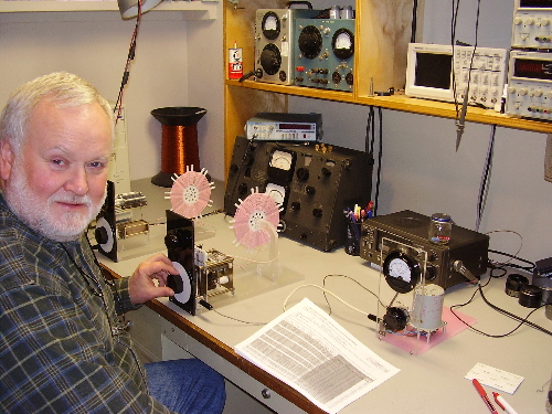
It was 1947. I was a young boy 8 years old living in Oak Grove, Oregon. I did not know it yet but my career and life work had begun. My grandpa helped me make a crystal set (radio). He carved a wooden form from a piece of balsa wood and covered it with wax paper. Then he wound a coil on that form using some enameled copper wire that my dad had brought home from the junk box at his work. I went on to build several more crystal sets and could receive three stations with my best one. With that insignificant beginning and Gods guidance, I had a wonderful a career in the field of electronics. I retired in 2001 - 54 years later, as a senior electromechanical engineer in the electronic test equipment field.
Both in my life work and my hobby as a radio amateur licensed as W7AUM and N7LZG, I have designed and built many receivers, transmitters, and other electronic test equipment, but I have never forgotten my first crystal set that grandpa helped me build.
In 2004, I came across an article about crystal radios on the Internet. It was referring to contests held to see who could receive the most stations with their crystal radios. Some of these radios were receiving more than 100 stations. That got me interested and I started digging deeper. This hobby sounded like fun. I decided to build another crystal radio. I discovered that there are lots of schematics, plans, and technical articles about crystal radios, all of which are variations and improvements to crystal sets made in the 1920's (that's 80 years ago!). There are many very creative designers that have discovered innovative electromechanical solutions to some difficult problems in these radios. Some of these radios are really high performance.
There are also some builders on the internet that make some outrageous claims that re-define physics and electronics.
I wanted to build a really high performance crystal set. To do this I needed to follow the basic laws of electronics and physics plus apply the latest advances in technology of the components that make up this radio. Many of the components that make up these radios have improved such as; the detector diodes, capacitors, and the insulation materials.
I wanted to make the best radio that I could and learn something at the same time. I did a lot of reading, research, and experimentation to build or obtain the best components that I could get. I started collecting parts and put my first set together in January of 2006 (59 years after my last one) and entered a contest with it. I have had lots of fun improving the design and bench testing my radios. One year later in 2007 I finished my second radio and the documentation below is for that second radio.
My Latest Radio
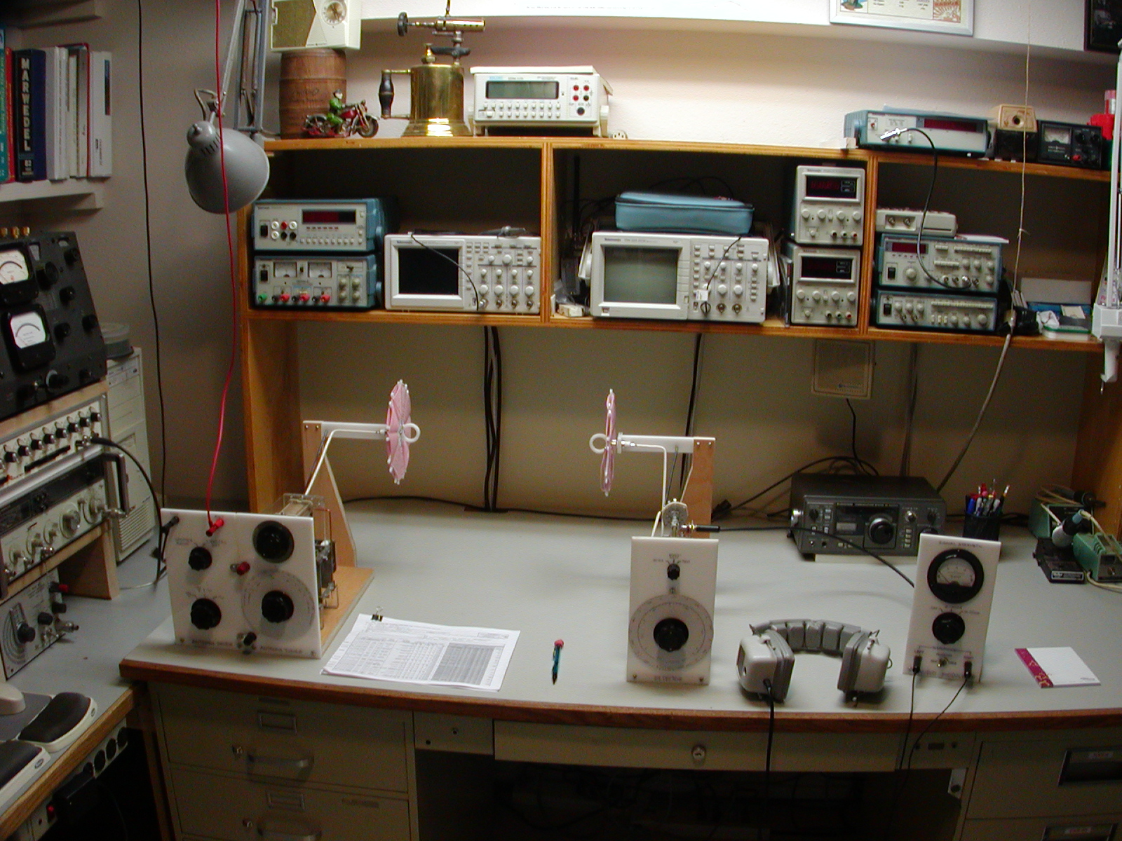
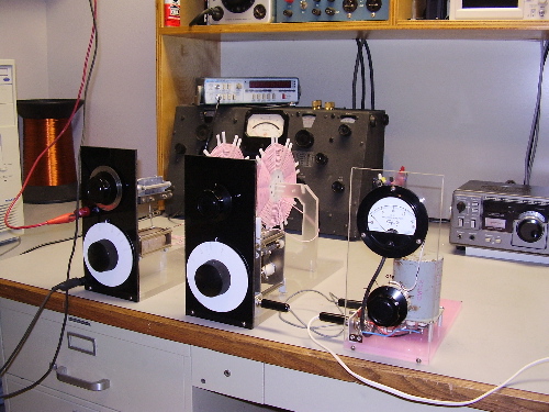
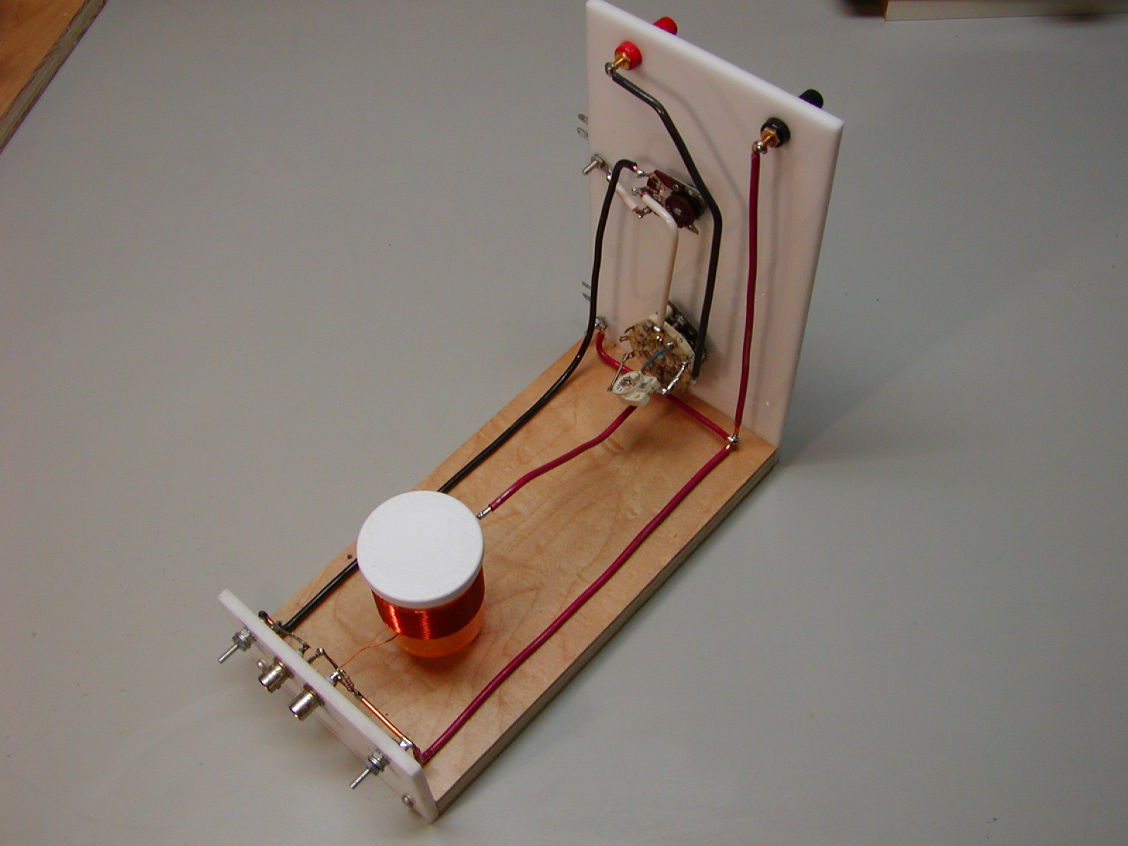
This is my latest crystal radio. As you can see, it takes up most of my work bench. I call it my set #2. It receives the AM Broadcast or Medium Wave band and it tunes 530 kHz to 1710 kHz. It is a very basic design using high quality components and materials. It is a "double tuned" design. That is, the antenna and the detector each have a tank circuit that is tuned separately.
Again, I used the modular design like last years set. In the above picture, from left to right are the Antenna Switch, the Antenna Tuner and Detector, the Audio Impedance Matching Module and the Headphones.
This set is basically the same circuit as the set that I used in the 2006 contest except for the addition of plug-in coils and different capacitors. I split the tuning range (530 kHz to 1710 kHz) into two bands: (A) 530 kHz to 1000 kHz and (B) 850 kHz to 1710 kHz. I avoided tapping the inductors to keep the Q as high as I could across each band.
Here in southwest Washington State this set receives more than 15 stations clearly in the daytime and almost every assigned 10 kHz channel at night. When this contests judging is completed I will Put my 2007 contest log here for you to view. See near the bottom of this page for a link to the 2006 contest log.
Antenna Tuner and Detector Schematic Diagram
Parts List
C1 - 350 pF variable capacitor with vernier drive (antenna tuning)
C2 - 460 pF straight line frequency variable capacitor (detector tuning) w/2 vernier drives
C3 - 47 pF ceramic capacitor (to remove any RF signal after the diode)
C4 - 430 pF variable capacitor (antenna impedance match)
D1 - ITT FO-215 germanium diode
D2 - Agilent HSMS282 Schotty diode (2 in parallel)
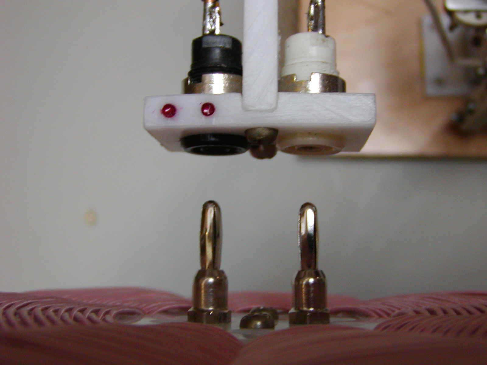
J1, J2, J3, J4 - banana jacks (mounted on 3/4" spacing)
J5 - BNC Connector (for testing)
L1A - 46 turns, L = 245.0 µH (at 530 kHz), 6.87" O. D.
L2A - 47 turns, L = 251.9 µH: (at 530 kHz), 6.93" O. D.
L1B, L2B - 29 turns, L = 86.6 µH: (at 850 kHz), 5.12" O. D.
P1, P2, P3, P4 - banana plugs
S1 - 2 pole 3 position rotary switch (diode selection)
Description
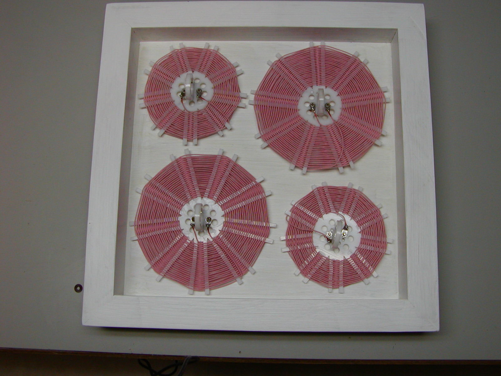
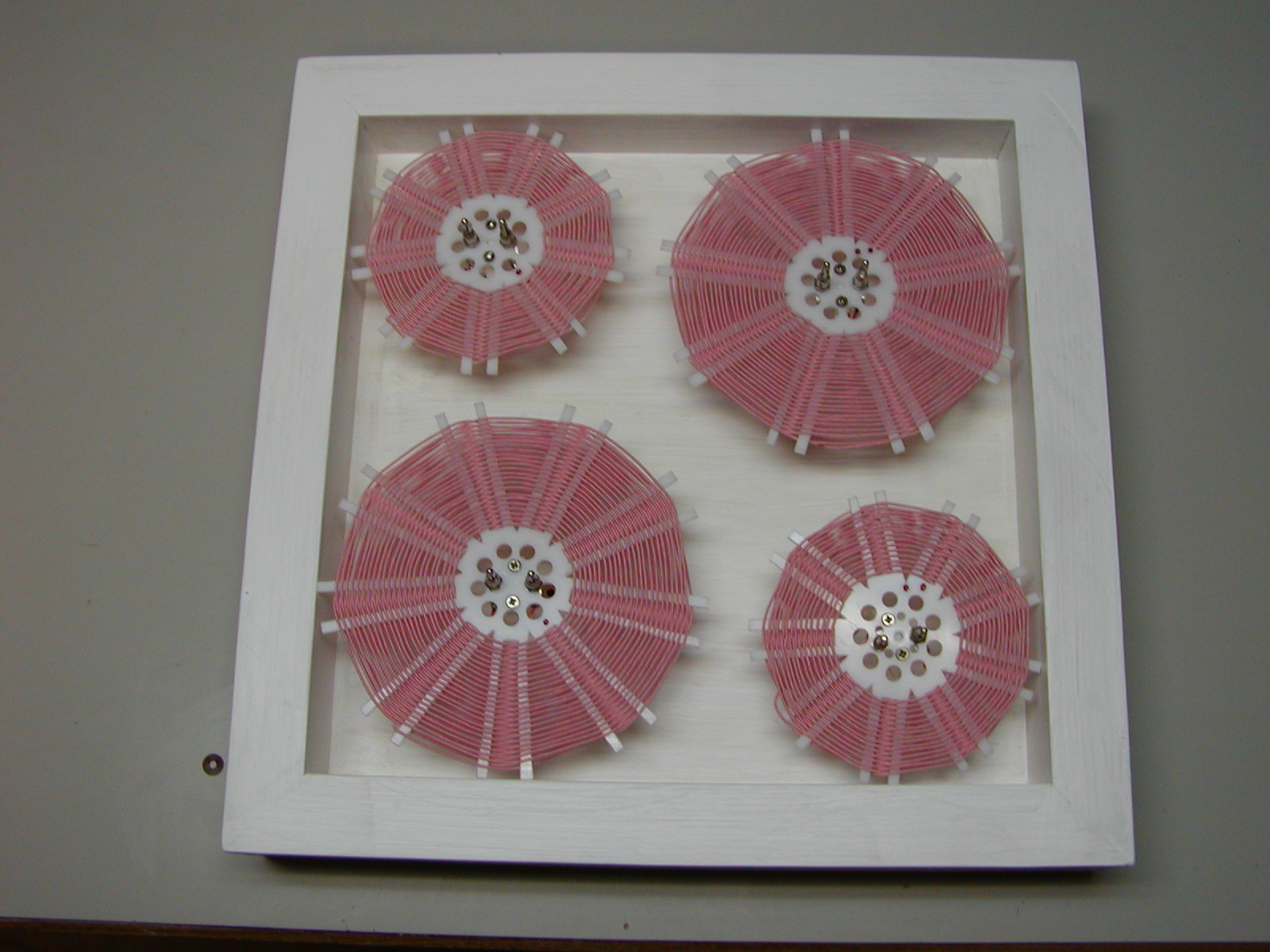
Coils:
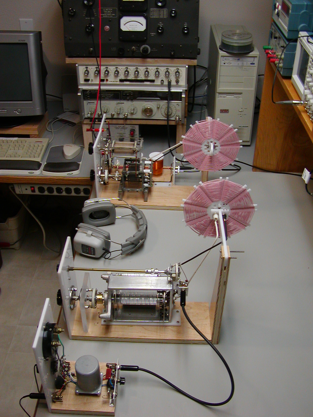
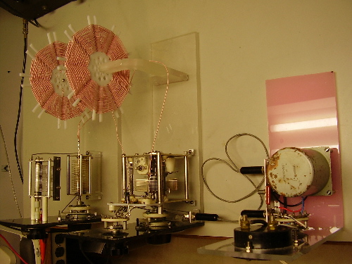
I decided to wind the coils using the "Spider Web" design. They are easy to wind, easy to support, they have low distributed capacitance, and provide high Q.
When connecting the start and finish windings of the coil to the set I connect the outside winding of the coils to ground or "cold" side of the circuit to reduce the capacitive coupling.
If you would like more information on the inductors I used in this set you can go to my page about The Inductors in my Crystal Set page. (www.thelenchannel.com/1xtal_coils.php) or My Spider Web coil forms page (www.thelenchannel.com/1xtal_coils.php)
Antenna Tuner Module:
The antenna tuner corrects the impedance mismatch from the antenna to the radio and allows the maximum available signal will be delivered from the antenna to the detector module. It also screens out a lot of unwanted stations, including harmonics from stations outside the band. It makes a definite improvement in the overall performance.
It uses a variable capacitor (C4) that is in series with the antenna to match the low impedance of the antenna to the high impedance of the antenna tank circuit (C1, L1). Tuning the parallel tank circuit (C1, L1) makes the antenna resonate at the desired frequency. Because the Q is reduced with more capacitance, selectivity can be maximized by reducing the value of C4 and then retuning C1.
Antenna Tuner to Detector Coupling:
Current flowing in the antenna tuner inductor winding (L1) produces a magnetic flux that is linked to the inductor winding (L2) in the detector. This flux is common to these two windings and is called Mutual Inductance. By moving the modules (coils L1, L2) apart and closer the degree of coupling between these two resonant circuits is adjusted. When the coupling is adjusted to where the maximum amount of power is transferred between circuits, that is called "critical coupling". At 1120 kHz (the band center) critical coupling occurs at 16 1/2 inches but it I operate the crystal set between 14 to 16 3/4 inches. I made some marks on my workbench to show the best operating locations for the antenna tuner and the detector module.
When these coils are closer together the sensitivity (signal strength) is better but the selectivity is less. Separating the coils improves selectivity but the sensitivity is less. It does help to adjust this distance slightly when trying to tune in some weak signals.
The magnetic and electric fields associated with this type of coupling are also affected by other nearby metal objects. Even objects within the radius of the coil everywhere (all directions) can decrease the coil Q by up to 20 percent. While making my measurements, I quickly found out the panels from my nearby test equipment and even the metal center drawer under my work bench top caused the bandwidth to get wider.
Detector Module:
The detector is also a parallel tuned tank circuit consisting of L2 and C2. I used a large capacitor from an old General Radio 1303-A Audio Generator that uses a good low contact resistance wiper to make contact with the rotor. All metal used in its construction is non-ferrous (aluminum, brass, stainless steel, and beryllium copper) to help in not coupling into the magnetic circuits.
The detector diode that I used for the 2006 contest was a 1N34A Germanium with a Diode Saturation Current of 680 nA and a output load of about 50 KΩ. At the present I am using a FO-215 Germanium Diode which has about 109 nA of Diode Saturation Current and about 250 KΩ of output load. The FO-215 is much louder on weak stations. An alternate diode (Agilent HSMS282 Schotty) can also be switched in to help when digging for that weak signal. The diode switch can also select a BNC connector (J5) to provide an output from the detector for testing. Any RF voltage passing through the detector diode is shunted to ground by the bypass capacitor C3. The connection is made to the Audio Impedance Matching Module with a 20 inch length of RG-59U.
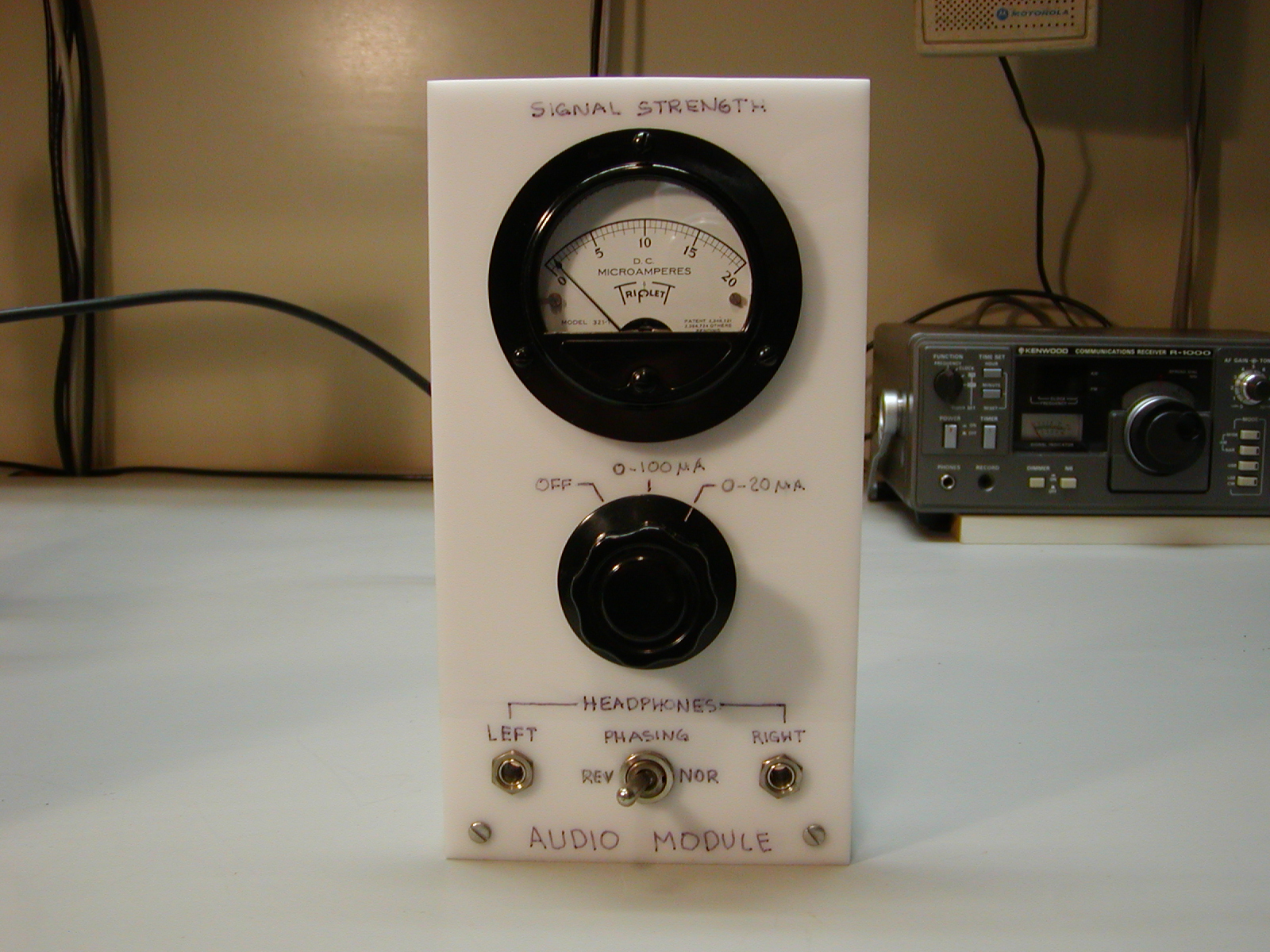
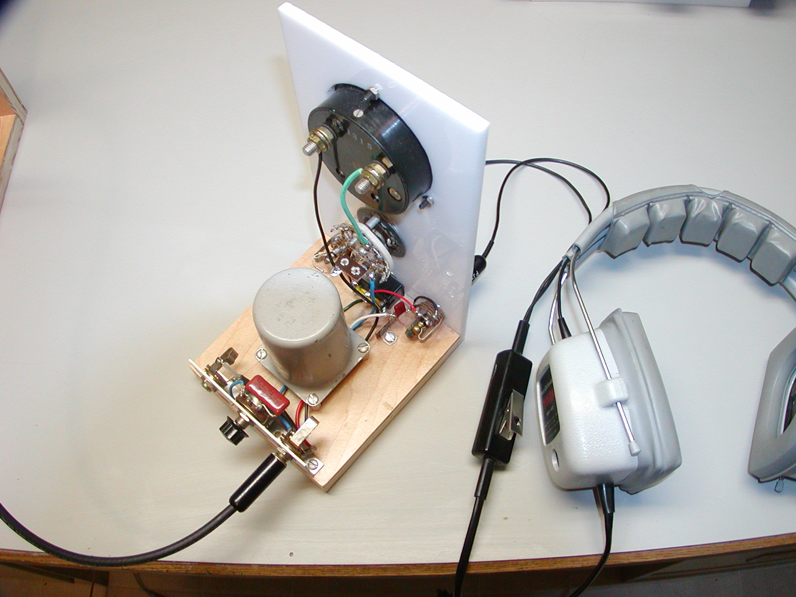
Audio Module and Headphones:
I did a good audio impedance match from the detector to the headphones for this set and the volume was louder in the headphones. It also made a difference in the being able to hear more of the weaker stations. If you are interested, you can check out my page for the description, schematic, and parts list for the Audio Module and Headphones. (www.thelenchannel.com/1xtal_audio.php)
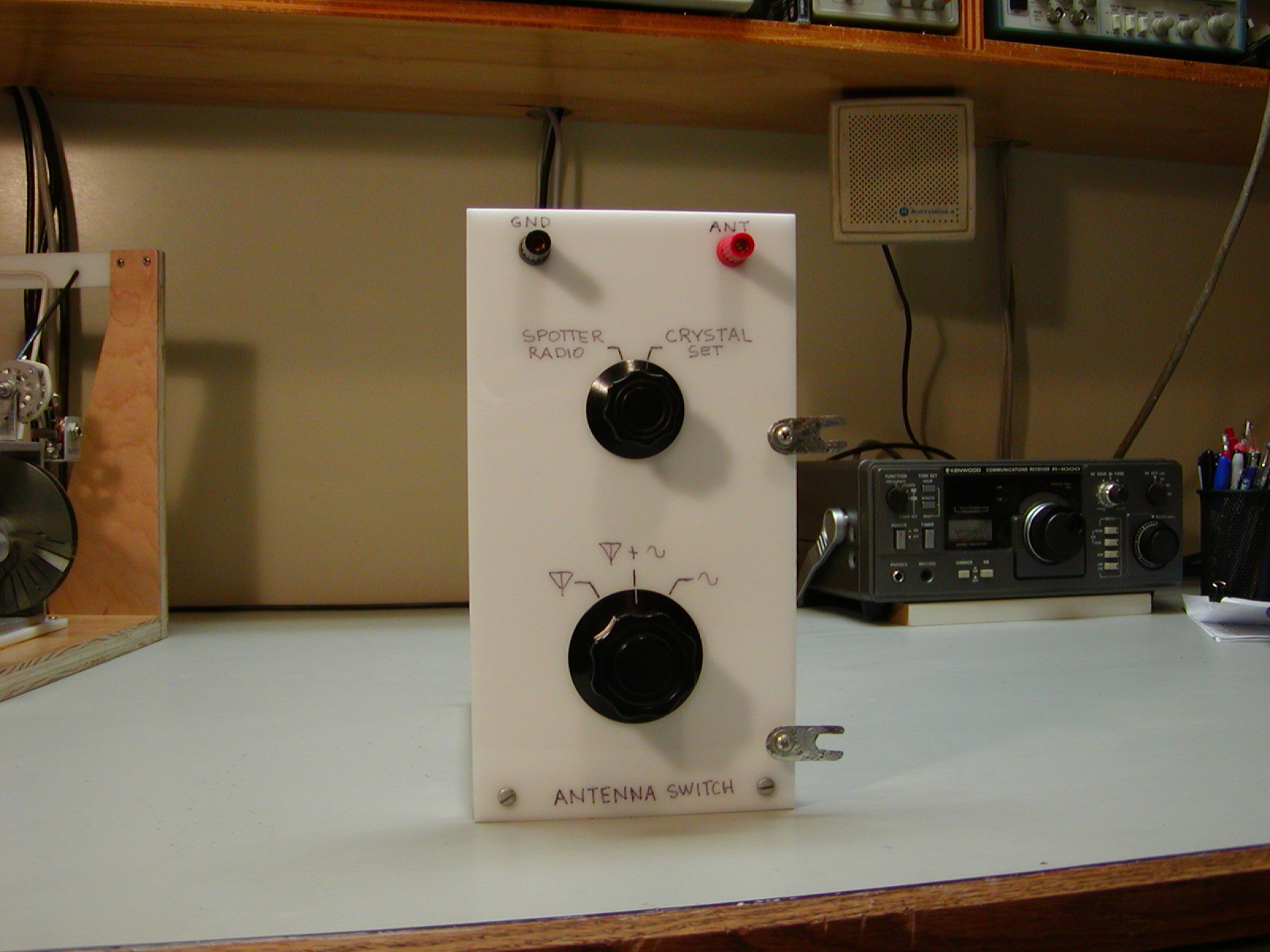
Antenna Switching Module:
This module is just a simple dedicated switching unit to conveniently switch the antenna input of the crystal set or spotting receiver to either; the antenna, an RF signal generator (signal source), or the antenna and signal source. Check out my Antenna Switching Module page. (www.thelenchannel.com/1xtal_antswitch.php)
Mechanical Design / Construction
My first plan was to build this radio into a wooden cabinet. But because of the losses in the tank circuits due to the proximity of the coils to other components, I could not calculate how big to make it until I after got it working. So I decided to build an "open construction unit" that is, I built it in a modular (prototype) design. This allows me to do testing and modifications easily on each section. Doing it that way also makes it easier to modify as I change the design or parts. After it is running to my satisfaction, I can empirically determine what size the cabinet needs to be.
Another benefit to the modular construction is that I can move the audio impedance matching module out of the magnetic field of the antenna and detector tank circuits. This module contains large magnetic materials (the transformer and meter) and if it is placed near those inductors it will reduce their coupling, and lower the overall performance.
I tried using plug-in coils this year. I found out with my last set that I needed to keep conductive objects away from the coils, and I needed to orient the coils so they were higher off the workbench. This year, I located them higher. I had to move them up to 11-1/8 inches from the center of the coils to the top of the workbench to eliminate the coupling from the coil to the bench top material. It looks odd but I am not giving up any performance due to them being too close. The connectors used for the coils are banana jacks spaced 3/4" apart.
I installed a vernier drive on the variable capacitor in the antenna tuner tank circuit.
Because of the split frequency range of the plug-in coils, I only used about 1/3 of the highest value of my capacitors which allowed me to use 2 vernier drives in series to tune the detector tuning. The total reduction ratio is 9:1. The 10 kHz channel marks on the dial are about 1/8 to 3/16 inch apart and each band takes up about 330 degrees of the dial. That makes it much easier to read exactly where the set is tuned.
I used Acrylic plastic (Plexiglas) and wood for the chassis parts. The Coil forms and supports are High Density Polyethylene (HDPE). You can read more about that material in my Spider Web Coil Form page. The plastic is easy to cut with the table saw and the scroll saw. It also has a fair dielectric constant. All the hardware in the crystal set is non-magnetic stainless steel or brass.
When I am satisfied with the performance, I would still like to build it into one nice looking wooden enclosure and move it out of my radio room into the living room. But for now, when it is operating, it still takes up most of my work bench.
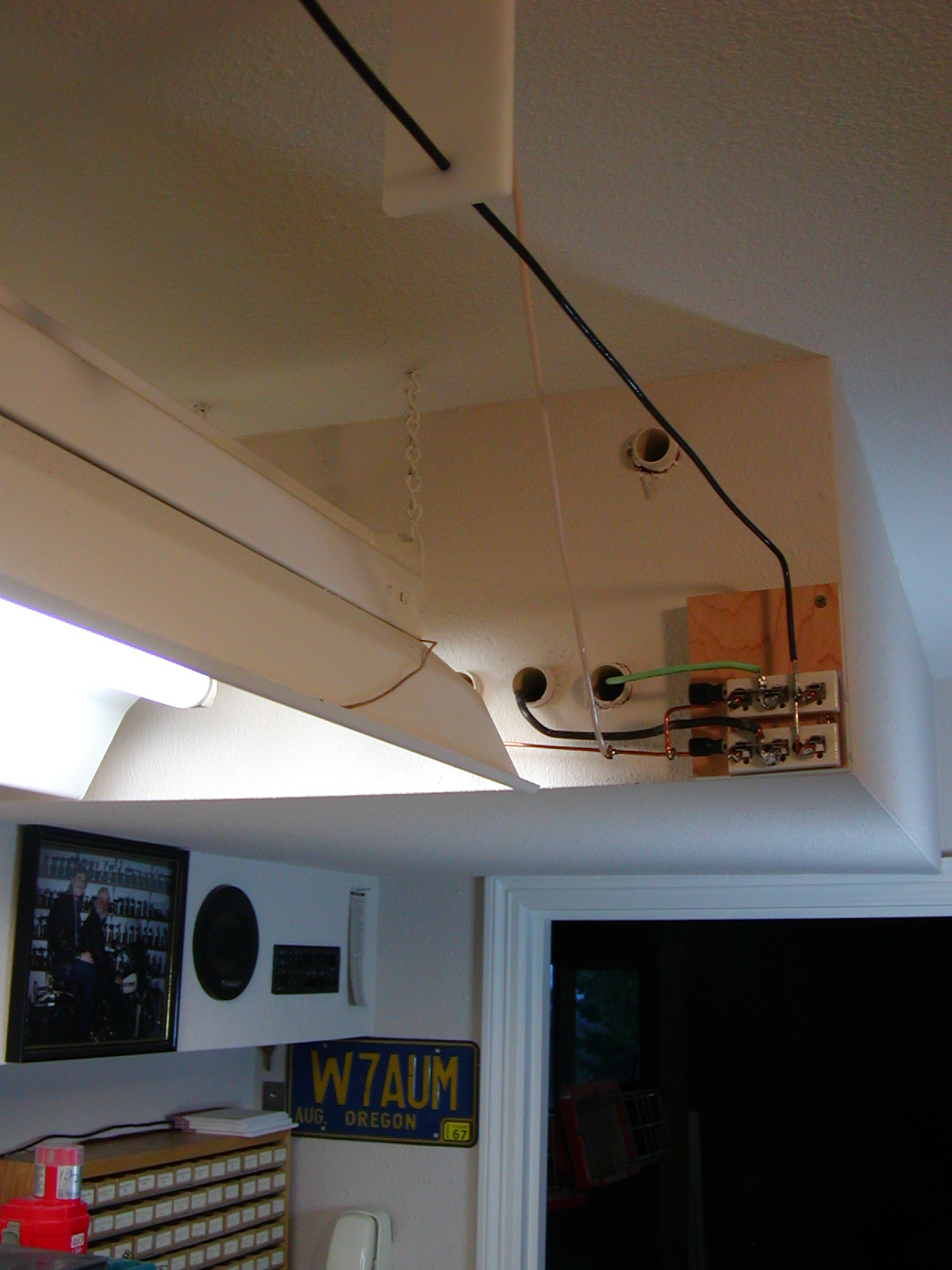
Antenna & Ground
Our location is at 600 feet elevation, up on a mountain, facing the South. My antenna is a simple inverted "L" non-resonant longwire. It is oriented from the East to the West and is 230 feet long. It starts out about 60 feet high in a fir tree and the other end is up 40 feet where it attaches to our house. I used AWG 8 stranded copper building wire (THHN) with 0.030" thick nylon-over-PVC jacket. It has lots of sag because it is very heavy. The antenna enters the house into 3/4" PVC conduit in the ceiling between the joists and it ends up over the workbench in my radio room ceiling. Next to this antenna lead-in termination I have also located my ground termination. I installed switches at this location so when I am not using the antennas, I can short them to ground. I attached test leads with alligator clips on the ends that hang down from the ceiling just above my workbench to make quick connections my radios.
This new antenna is 6 times longer than the one that I had last year and it has 3 to 4 times more signal as measured on my crystal set signal strength meter.
For the earth ground connection, I drilled a hole through my radio room concrete floor in the basement and drove an 8 foot ground rod into the dirt below.
Stations Received
We live in Woodland, Washington 23 miles north of Portland, Oregon. During the daylight hours of winter I can hear all the local stations from Portland, OR and Vancouver, WA; one San Francisco station (KGO); and two Seattle, WA stations. In the night I can also hear: most of the stations from Seattle, WA (100 Miles away); All the higher power stations from San Francisco (580 miles); Several stations including (KFI & KNX) from Los Angeles (870 miles); (KOA) in Denver, CO (1014 miles); (KTWO) in Casper, WY (844 miles); and two stations in Mexico south of San Diego, CA (1400 miles). My greatest distance was in the 2007 crystal radio contest which was WOAI in San Antonio, TX (1,750 miles)
2007 Crystal Radio Contest
This was my second year for entering the Birmingham, Alabama Crystal Radio Group Annual Elmer Memorial Crystal Radio DX Contest. It was held January 12-22, 2007.
Besides disrupting my sleep schedule, one of the harder things of the contest is enduring the many hours of concentrated listening to all the trash talk on the talk shows waiting for station breaks and identification. It is very exciting though to hear a weak station that is fading in and out respond with a call sign from a really distant location. On the stations that I logged, I was very careful to make sure that I could hear and understand every one on my crystal radio.
Some of the stations that I heard in last year's contest I could not hear this year but overall I heard more stations from greater distances this year. Several things might have helped this happen.
1. The new antenna.
2. A better detector diode
3. The addition of my antenna switch made the tuning procedure easier.
4. Properly impedance matching my headphones to my set
5. The propagation might have been different than last year.
6. The biggest thing was that I was learning to receive DX.
During the contest I found that I had some interference generators in my own house. We have several low voltage lights with dimmers that generate lots of RFI (Radio Frequency Interference). So if one of these lights got turned on while I was listening, I knew it immediately. I also had to turn off our computer and unplug the cell phone charger, and a VCR and TV in the basement.
I will be posting my station log for the 2007 contest after the contest results are reported.
Here is a copy of my 2006 Certificate of Participation for the contest.
What's Next
I don't plan on building a new crystal set for next year as I am happy with the performance of this one.
The results of my bench testing show that the bandwidth is what I desired and the sensitivity is the best that I am able to do (which is adequate). I don't think that I am able to improve the overall performance by building a new or different radio.
My results in this years contest tell me that it's working when hooked up to an antenna and ground. If I were to spend more time learning DX tips, listening, and logging I am sure that I could hear many more stations, but I don't believe that is a measure of how good my crystal set is. I also have what I believe to be a very good location for antennas, but that doesn't make my crystal set better either.
My plan is to build the crystal set into one package that was as small as possible without affecting the performance of the inductors. Then build it into a nice looking wooden cabinet and move the whole thing into my living room.
This hobby has been extremely fun and since I am retired, it satisfied my desires to challenge my mind in the technical area. Also, I have found that I can still have the technical personal relationships that were so enjoyable in my life work.
If you the reader are considering building a crystal set I would like to encourage you to do so. There are groups that you can get involved in on-line to help you with any problem. Crystal sets are for ANY level of skill and knowledge.
Photos and local links
Here are some of the photos and documentation used on my crystal set.
Crystal Set Web Links
Credits and References
I want to give a special thanks to, Dave Castro. He is a great RF Electronic Engineer, co-worker, and friend who also lives in Southwest Washington State. He donated some nice test equipment to help me to do several of the tests more accurately. He also took the time and repeated himself enough times to give me a better understanding of Resonant Circuits and Impedance Matching. It was his suggestion that I use plug-in coils. Thanks Dave.
Also, to Dick Kleijer from the Netherlands. He is a competent, practical, engineer who presents the subjects and data in a way that is easily understood. His paper on coupled circuits is excellent.
At least one of the following textbooks is usually lying open on my desk or workbench at all times:
1. RF Circuit Design by Chris Bowick (1982).
2. Electronics & Radio Engineering, 4th ed, Terman (1955).
3. Electronic Designers' Handbook, Landee, Davis, Albrecht - McGraw Hill (1957).
4. Electronic Measurements, Terman & Pettit - McGraw Hill (1952).