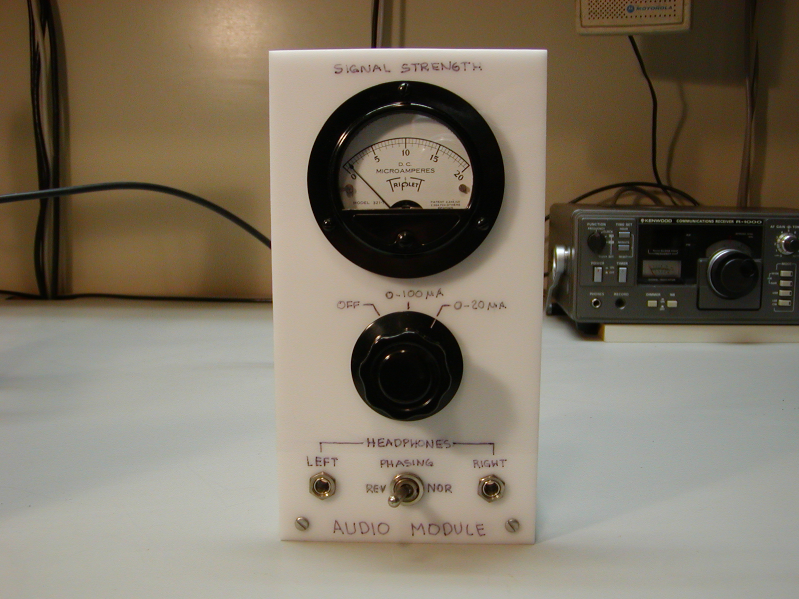
Audio Module and Headphones
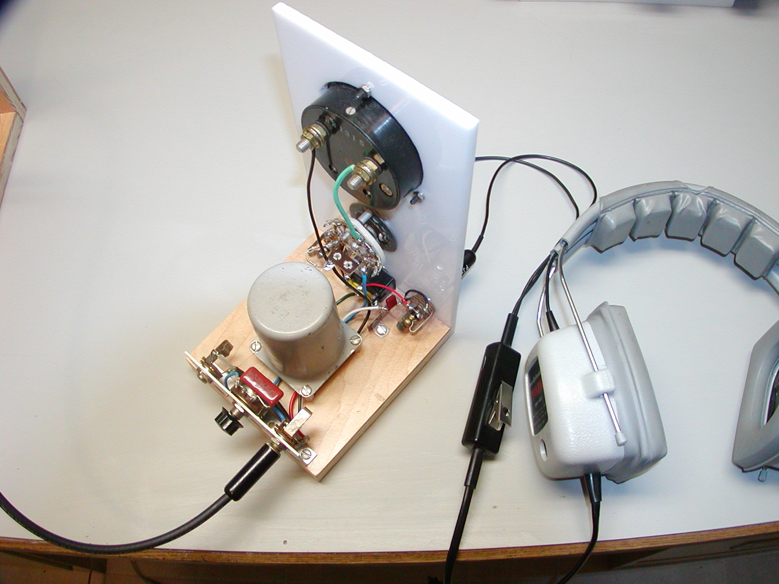
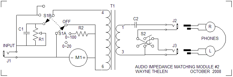
Matching the output impedance of the crystal set to the headphones is necessary as the tank circuit with diode consist of an impedance of about 200 KΩ. If the headphones were also 200 KΩ that would be a perfect match, but the headphones are only 1200 Ω (two 600 Ω units in series). I used a high impedance audio transformer that I found at a Ham swap meet that matched both my detector and headphones. Without this impedance matching transformer these low impedance headphones would lower the "Q" of the tank circuit and ruin the performance of the set.
Audio Module
There is also a Signal Level Meter in this module. It was such a big help in last year's contest I decided that I would keep it in my set. I used a vintage Triplett DC microampere meter that measures the current in the diode on the cold (grounded) end of the transformer. I choose to measure the current rather than the voltage across the transformer because it needs a high impedance meter for measuring voltage or it will load the circuit down. However, I can see on the scope that it still loads the set down slightly when in use so I have a switch to disable it from the circuit when desired. When listening to a station with the meter showing 1/2 µAmp current through the diode, the signal is still understandable. This is a great tuning aid for adjusting the set and I highly recommend it to anyone considering using one.
The "Benny"
This part of the circuit has been suggested by Ben Tongue in his article number 01. It includes C1 and R1. It enables the diode DC load resistance to be made equal to the AC load impedance. This reduces audio distortion and improves selectivity on strong signals. When the meter is turned off, the Benny is on.
Schematic Diagram
Parts List
C1 - 0.1 µF Capacitor (the Benny)
C2 - 1.0 µF non-polarized Capacitor (selected for best sound and bass response for my headset)
J1 - 1/4" Phone Jack (200 KΩ input from crystal set)
J2 - 1/4" Phone Jack (output to Left side of headphones)
J3 - 1/4" Phone Jack (shorting)(output to right side of headphones)
M1 - 0-20 DC microampere meter
R1 - 250 KΩ Pot (the Benny)
R2 - 549Ω (0 - 100 µA meter range)
S1 - SP3T X 2 Rotary Switch (meter range switch)
S2 - DPDT Toggle Switch (headphone phasing switch)
T1 - Audio Input Transformer - 200kΩ primary - 1kΩ secondary
Headphones
The Sound Powered "balanced armature" earpieces from post-WWII military surplus sound powered handsets that are mentioned so much on the internet now are really a good match for a crystal radio using an impedance matching transformer. I used two United States Instruments Model #A-260 UA1614 earpieces that I selected for volume and clarity from several that I had and installed them in an old aviation pilot's headset. They are comfortable to wear and block out lots of outside acoustical noise.
Headphone Phasing
The two earpieces in the headphones are connected in series and wired so that a positive voltage causes both earpieces to push air toward the ear simultaneously. This is similar to audiophiles who connect their speakers to match the phase of the broadcast or recorded signal. This matching is referred to as "in phase". It makes the audio sound like it is located inside your head rather than at each ear. My personal preference is to use this "in phase" mode most of the time as it seems clearer to me. I have a DPDT switch that reverses the leads on one earpiece to cause one to push and the other to pull thereby making the earpieces "out of phase". When I am trying to dig a weak signal out of many others just switching this "phasing reversal switch" gives a little difference to my ears and can make the difference in whether I can identify the station or not.