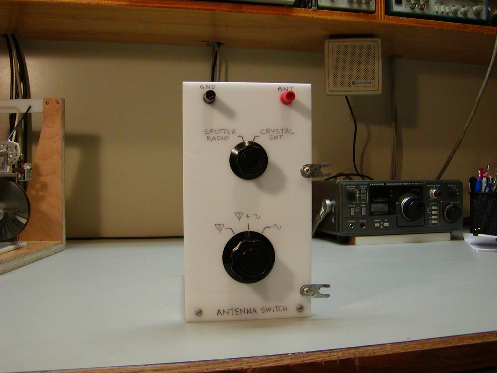
Antenna Switching Module
I built this module toward the end of the 2006 crystal set contest when I found myself connecting and disconnecting many wires and cables each time I wanted to set my crystal set to a specific frequency or check the frequency of an unknown received station.
This is just a simple dedicated switching unit to conveniently switch the antenna input of the crystal set or spotting receiver to either; the antenna, an RF signal generator (signal source), or the antenna and signal source. It is also a very valuable tool to make it easier to operate during the contests and it keeps the workbench less cluttered.
Schematic Diagram

Parts List
C1 - 200 pF Silver Mica Capacitor
C2 - 3 - 45 pF Ceramic Capacitor
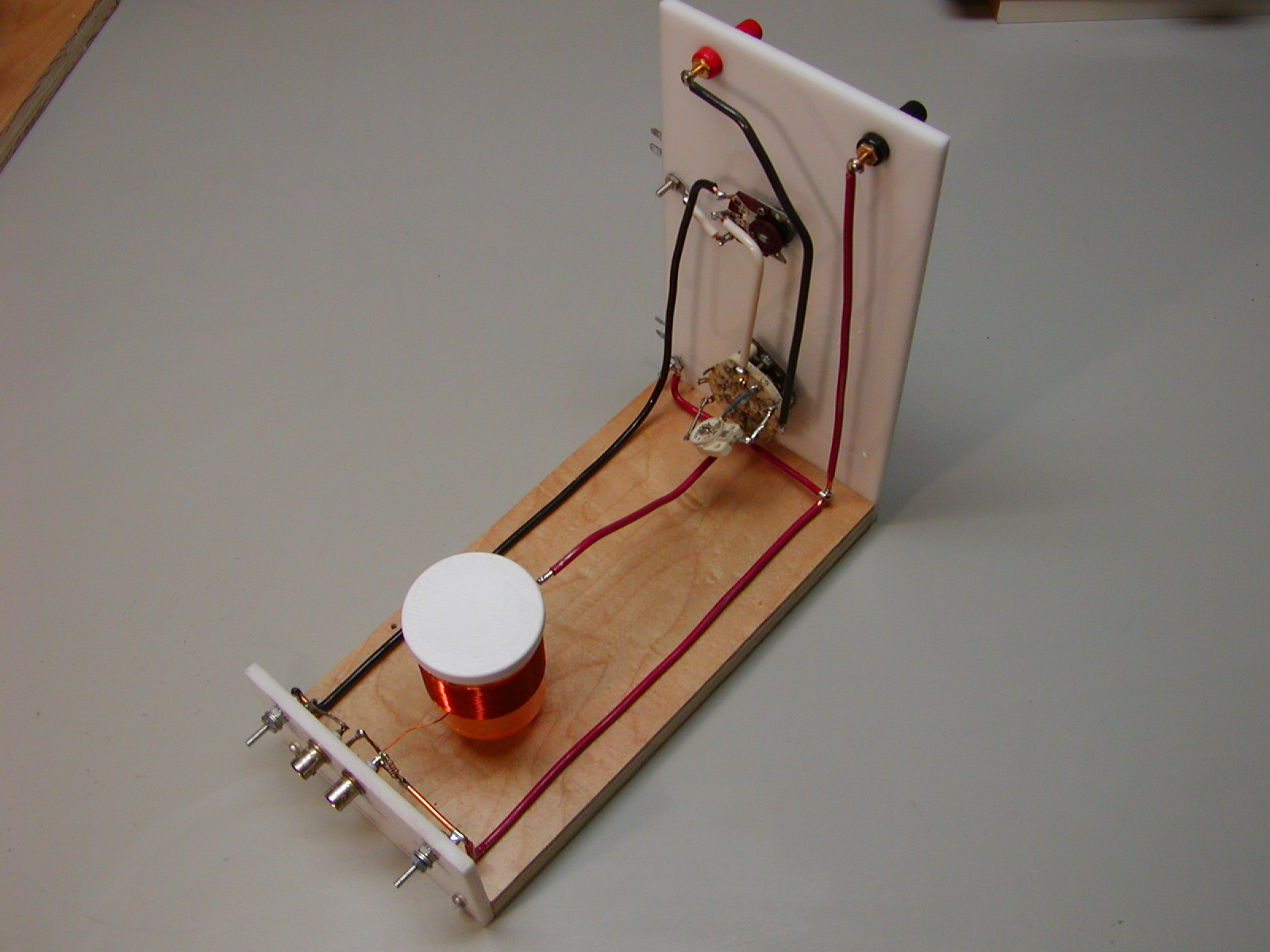
L1- 17 Turns No. 20 wire on 1 1/2" O.D. form (Polypropylene prescription bottle), L = 20 µH.
R1- 50 Ω Resistor
S1- SP3T X 2 Rotary Switch
S2- SPDT Rotary Switch
Operation
After connecting the wires and cables once, I just have to turn a switch to select between the crystal set or spotter radio. A second switch selects what source I want to apply: Antenna, Antenna & Signal Source, or Signal Source alone. The Antenna & Signal Source position allows the radio to receive a station off the antenna while a small amount of signal is injected. I use this position when checking the frequency of unknown stations or setting the crystal set exactly to particular frequency then shutting off the source and wait for a station to come in.
I also use this module for switching the frequency synthesizer in and out during characterization of the set.
This module includes an antenna "dummy load" (artificial antenna) when the signal source is selected. This makes the impedance that the crystal set sees when on the signal source to be similar to that of the receiving antenna. The tuning calibration remains closer the same as it would without this load. This dummy load is described in Electronic and Radio Engineering McGraw-Hill, 1955, F. Terman, pp. 944.